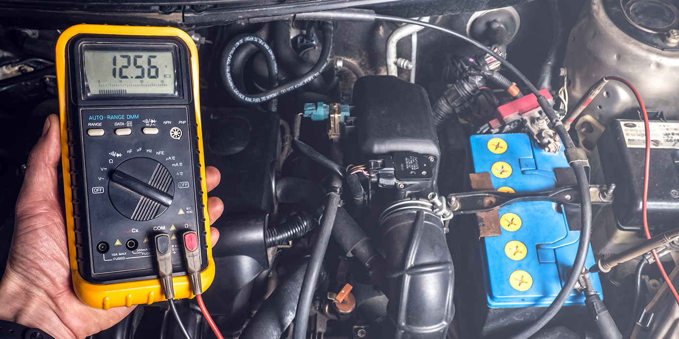
There was once a time when all a technician needed to diagnose a battery was a voltmeter. You could measure battery voltage, charging voltage and maybe perform a full field test. But charging systems have changed. The alternator is now managed by the ECM for loads and fuel economy. Testing now requires a scan tool.
If only battery voltage is present at the battery on a running engine, does this mean the alternator is “bad”? No, it does not. That only means that the alternator is not charging — but does not reveal why. Therefore, it does not prove a faulty alternator. All too often the alternator is condemned by technicians due to this test alone.
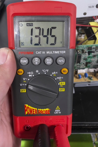
For some vehicles, it’s normal to see a reading as high as 15 volts. For others, it’s normal to see as low as 13 volts. For some, a constant 13.6 volts is an indication of a problem. Still yet, it’s perfectly normal for others to see the alternator not charge at all intermittently. Some alternators are controlled only with an internal or external regulator. Some are controlled only by the PCM. Still yet, others are controlled by a voltage regulator and the PCM. Not knowing what controls what and how it is supposed to function, can cause a misdiagnosis or a critical problem to be overlooked. Take the time to look at the service information.
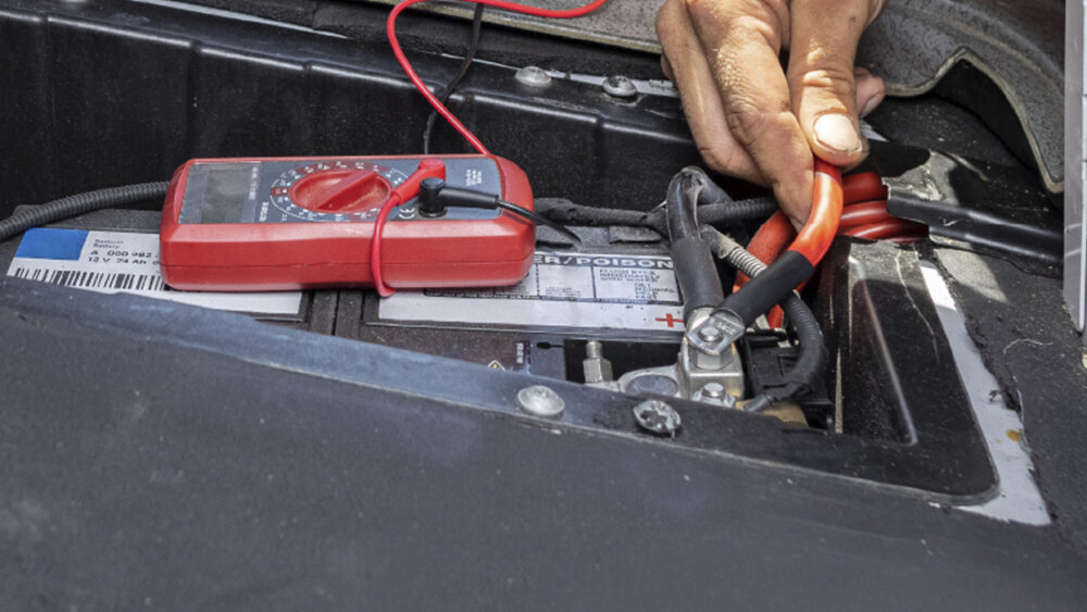
If you don’t see at least 13 volts when you check charging voltage at the battery with the engine idling, check the wiring connections at the alternator — not just visually or by wiggling the wires or connectors, but check for excessive resistance by doing a voltage drop test. Many so-called alternator problems turn out to be nothing more than a bad connection at the alternator or a bad wiring harness.
If communications were lost between the PCM and alternator, the PCM would turn on the battery light, but the regulator would still charge the alternator at about 13 volts. The PCM would set a trouble code relating to that loss of communication. Imagine trying to diagnose a battery light that doesn’t appear to have any reason to be on. That is, it doesn’t appear to have a valid reason until a scanner is added to the testing.
On many vehicles, the PCM is controlling the duty cycle of the alternator. It is controlling the amps and voltages in finer increments than can be measured by a simple meter, so that current is supplied in a more efficient manner. These changes might be just 10 milliamps, so connections to the regulator are critical. You cannot afford a mediocre connection.
Depending upon ambient temperature, charging voltage generally varies between 14.8 and 13.5 volts. The actual charging voltage designed into a voltage regulator is dependent upon factors such as how far the alternator is located from the battery and the ambient air temperature surrounding the battery as calculated by the PCM. Under normal operating conditions, an alternator should maintain about 14.2 volts at 70° F ambient air temperature.
As a rule, the key-off current drain on most late-model vehicles should be less than 50 milliamps (mA). But on some vehicles, it might be normal to have even greater draws for up to 10 minutes after the keys have been removed from the ignition. During this period, the serial data buses could be communicating and performing some digital housekeeping. Also, systems like air ride, the evaporative emissions system and auxiliary water pumps could still be active long after the vehicle has been parked. This is why on some modern vehicles service information, an OBD II breakout box and a scan tool are necessary to solve some intermittent parasitic power drains.
Extra Ground, Extra Trouble

It is a bad practice to use the positive and negative battery terminals to power aftermarket accessories on some late-model vehicles. The extra ground and power changes the internal resistance of the battery. The extra connections can cause the battery to incorrectly report the state of discharge, despite a normal battery condition. This can cause the battery to be overcharged and/or codes to be set that may cause the charging light on the instrument cluster to illuminate.