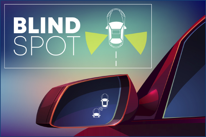
Blindspot detection was one of the earliest Advanced Driver Assistance Systems (ADAS) features offered on vehicles. The system alerts the driver to objects in the blind spot of the vehicle. Servicing these systems is straightforward to diagnose and repair.
Theory and Operation
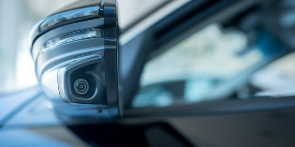
Blindspot detection systems can use radar or cameras, and some systems use both. The radar sensors emit radiowaves that bounce off objects and are received by the sensor. The sensors are mounted in the rear bumper. Camera systems will have cameras mounted to the side mirrors or A-pillar. The image from the camera is processed by a computer to classify the object. Some systems will use both radar and camera sensors to make a more accurate classification.
This information is processed to ensure the object in the blind spot is a vehicle, guard rail or pedestrian. The more info provided by the camera and radar, the fewer false alerts.
The blind spot sensors can also be used as a cross-traffic detection system. These systems extend the range of radar sensors to detect vehicles when they are in reverse.
Inputs
Radar sensors have a range that starts at the rear of the front doors up to 20 feet behind the vehicle. Some sensors used for cross-traffic detection can extend the range of the sensors up to 230 feet. Most radar sensors process the signals internally and communicate with a module.
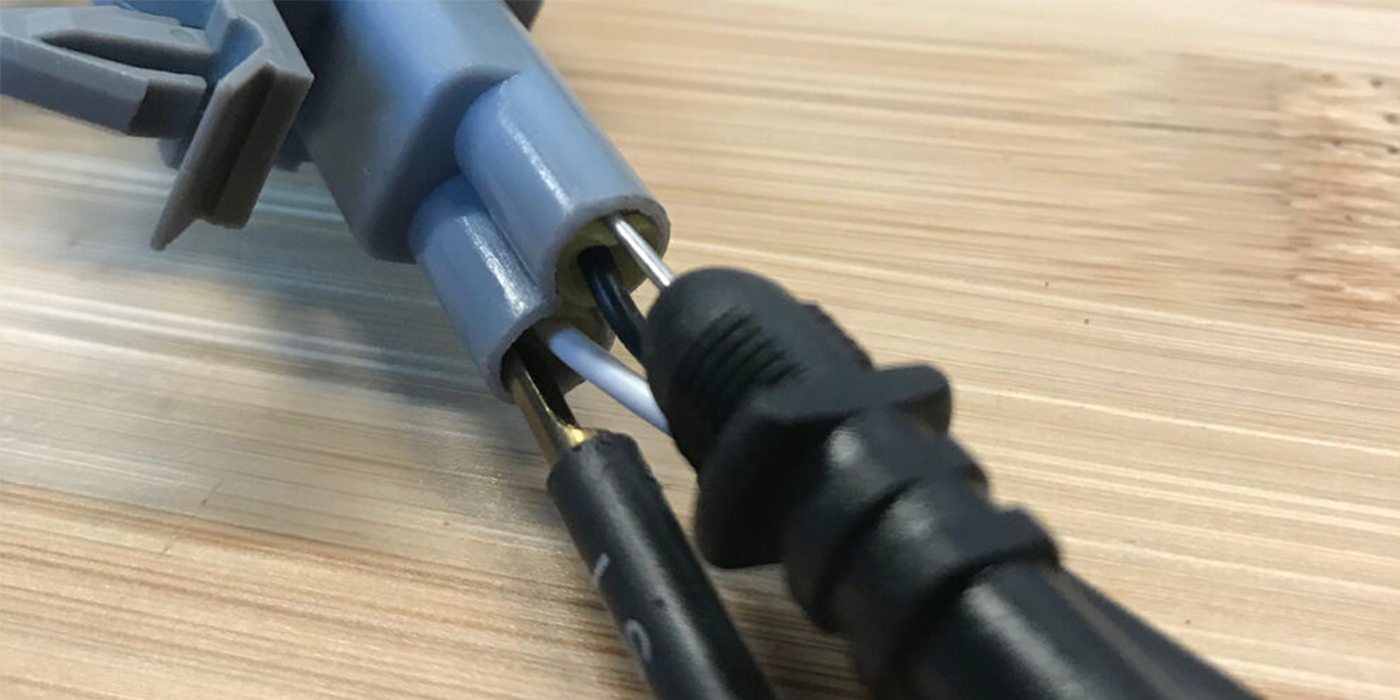
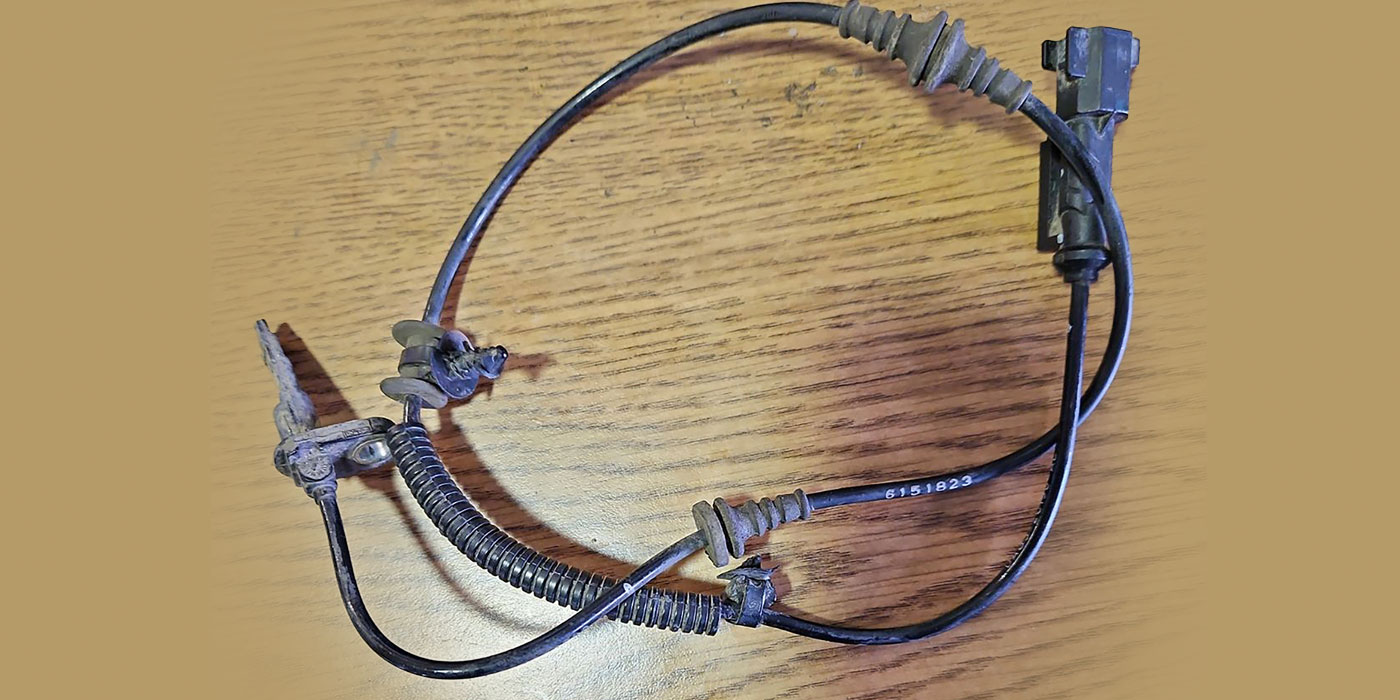
Cameras have what could be called a “fisheye” lens. Cameras must be able to capture images during the day and night. The images from the system are processed by a camera module and can determine if an image is headlights, road spray or snow. The cameras have a shielded cable that carries the signal from the camera to the module.
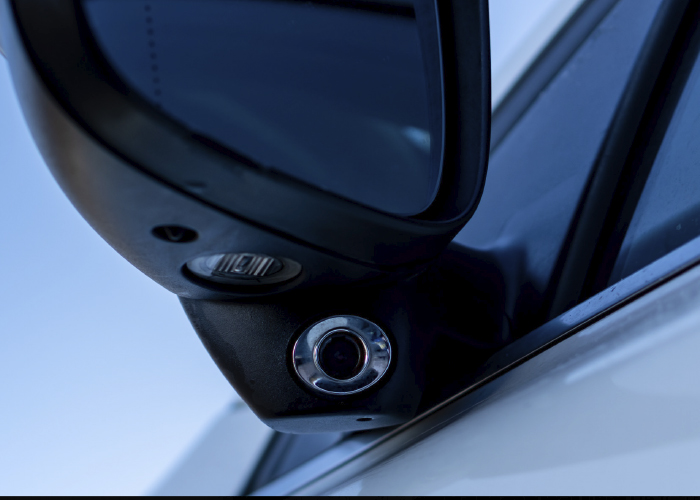
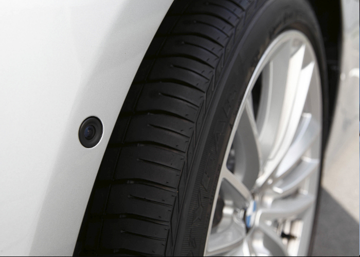
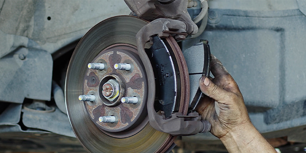
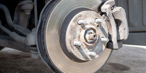
Cameras and radar sensors are typically located in impact-prone areas. Cameras are typically in the sideview mirrors. Radar sensors are often behind or attached to the back of the rear bumper cover. These are some of the most prone areas for impacts. Always make it a point to visually inspect the vehicle and sensors for damage. Look for how the bumper covers line up with the rear quarter panel or how the mirrors sit on the door.
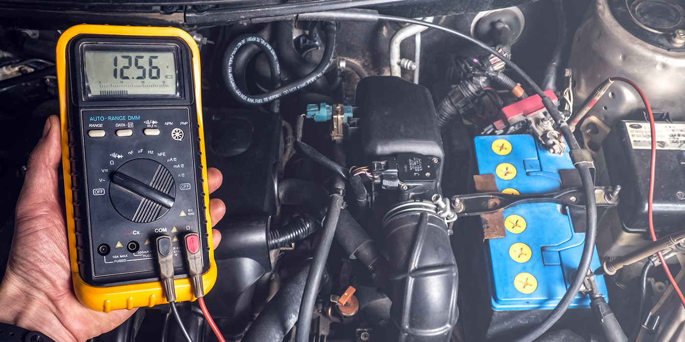
Vehicle speed is an essential piece of data for radar and camera sensors. For the blind spot detection sensors to work, the vehicle has to be moving. For most vehicles, the speed is around 5 mph. How the system processes the inputs from the sensor changes as vehicle speed increases.
GM vehicles will also use GPS to control the radar components of the system. For example, if a vehicle enters the Radio Astronomy Zone or National Radio Quiet Zone in Maryland, Virginia and West Virginia, the blind spot detection will deactivate. These zones have very little background radio interference. The zones have both astronomy and military applications.
Outputs
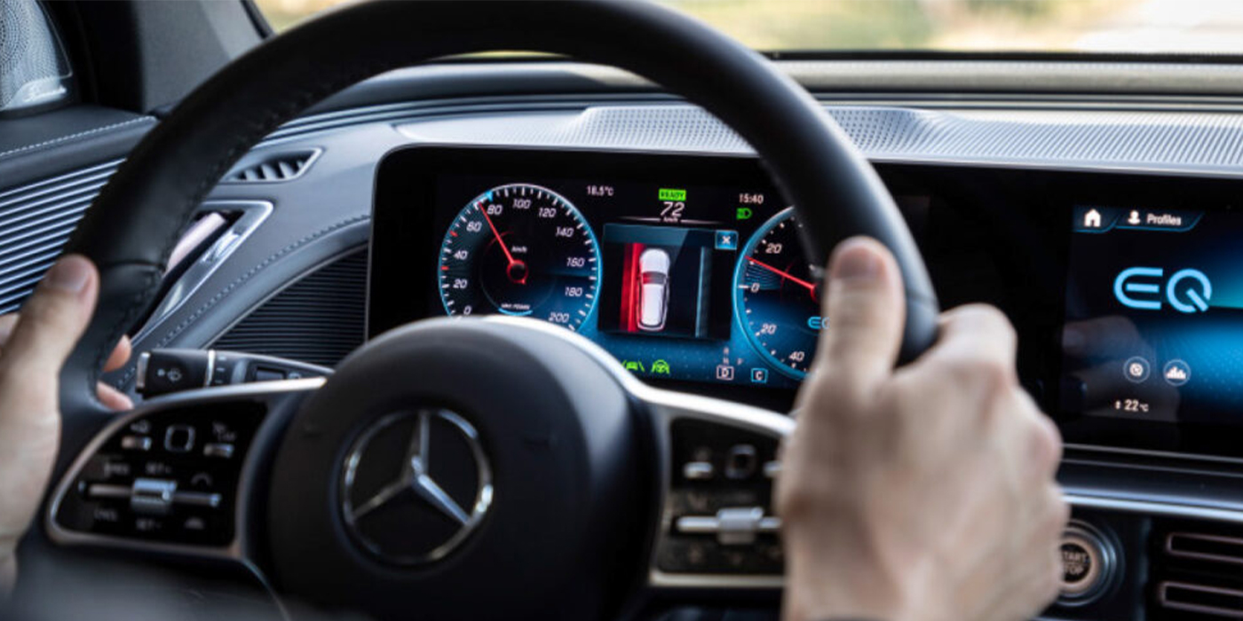
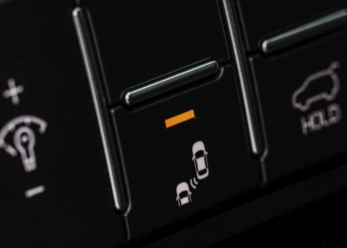
Every system uses warning lights in the sideview mirror glass to alert the driver to objects in blind spots. Some vehicles will give audio alerts. The infotainment systems on most vehicles are used to alert the driver of objects in the blind spots. The audio alerts can be sent to different speakers depending on the location of the object. Some vehicles may use a seat shaker to alert the driver. Some vehicles will shake the steering wheel.
Early blind spot detection systems had issues with false alerts. Many drivers became annoyed with the systems and turned them off or turned down the sensitivity. More advanced systems use radar sensors, cameras and information from systems like the lane departure. More data and faster computer processors have decreased the number of false alerts.
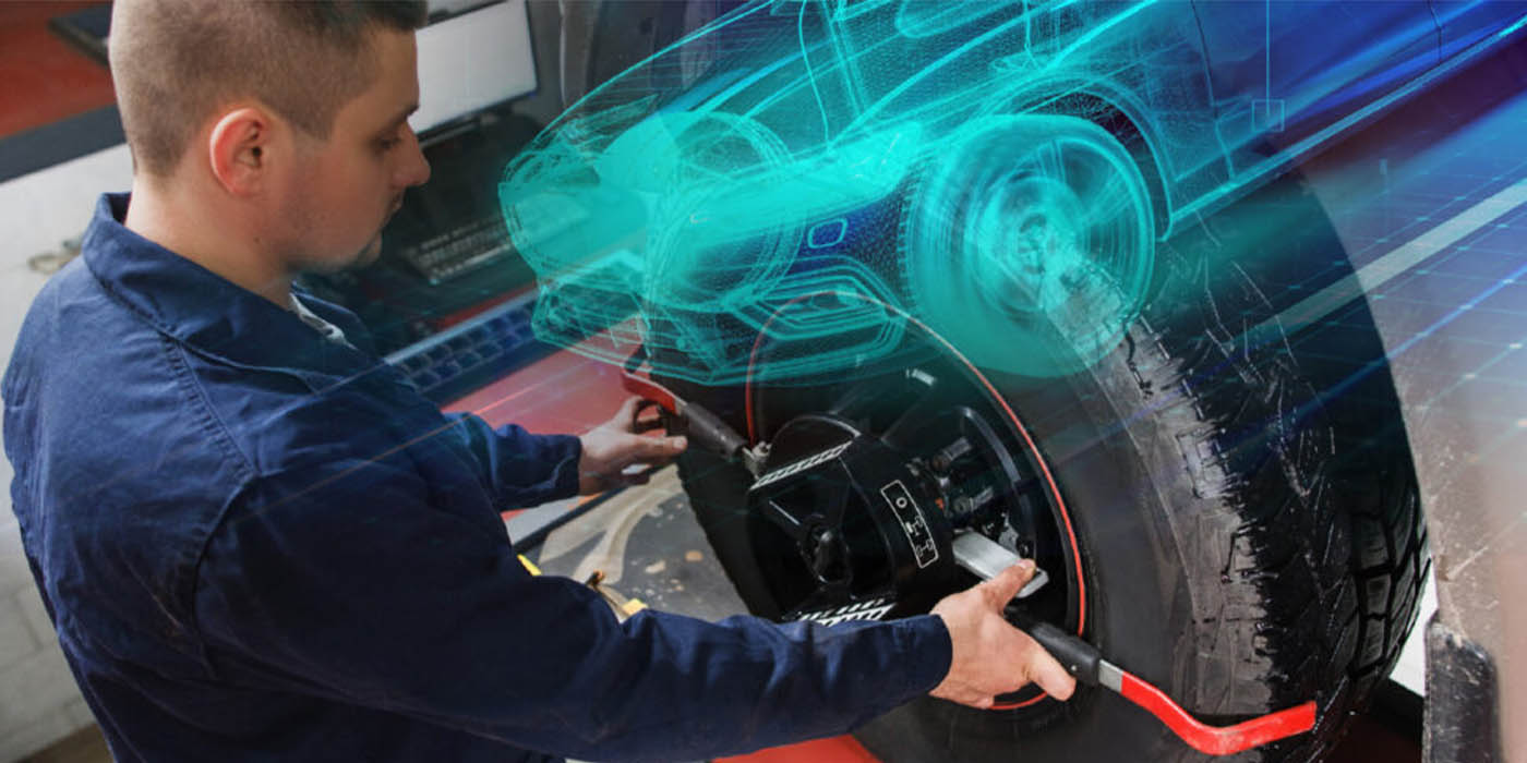
Calibration
Most radar sensors have a self- or dynamic-calibration procedure. This procedure may require a scan tool to initialize the process and a test drive.
Camera systems may require calibration if the unit is replaced or moved. Some of these calibration procedures require target mats to be placed on the floor next to the vehicle. The process will require a scan tool to initiate the calibration procedure.