MacPherson struts were first used on cars in the 1960s. Since then, struts have been installed on everything from compact cars to full-size trucks. The strut we know today was invented by Earl MacPherson as an alternative to the short-long arm suspension.
Accountants liked Earl’s struts because they eliminated suspension parts. Engineers liked struts because they were the perfect packaging solution for transversely mounted engines and transmissions. For shops in the 1970s, struts created new service and alignment challenges.
Eliminating the upper control arm changed how the camber, caster and toe increased or decreased as the suspension was compressed. The shorter arm on a conventional short-long arm suspension operates on a tighter arc than the lower long arm, so negative camber is induced as the suspension is compressed. With a MacPherson strut, the camber gain is minimal when the suspension is compressed.
Struts also changed steering geometry. The inward tilt of the strut is part of the steering axis inclination (SAI) angle, and is determined by the lower ball and upper strut mount. The backward tilt establishes the caster angle. SAI also helps to set the camber angle during turns.
The other unseen angle is the scrub radius. The scrub radius is the distance in front view between SAI and the center of the contact patch of the wheel, where both would theoretically touch the road. It could be positive, negative or zero. Engineers will optimize SAI and the scrub radius to improve steering feel, braking stability and even torque steer.
These angles are why it is essential to examine the front suspension for bent parts when diagnosing a steering or tire wear-related problem. It is also why a brake pull could be an alignment and suspension problem.
Under extreme forces, the strut can bend near its connecting point on the steering knuckle, or the piston rod itself can bend. The knuckle can also deform and change the angles. Either condition will cause the camber angle, SAI and the scrub radius to change.
Engineers will also design the shape of the knuckle to optimize SAI, scrub radius and the forces on the dampener and spring. For example, if you look at the steering knuckle on a Ford Focus or a VW Golf Mk4-Mk7, it pushes the lower mounting point of the strut inboard. The L-shaped knuckle does allow for wider wheels and tires, but it also controls side loads on the dampener and spring. The springs on these applications can have a barrel shape and contact the upper and lower spring perches in a very specific pattern.
If suspension damage is suspected, begin by checking the wheel alignment and performing a visual inspection. Suppose the left front suspension is well within specification, and the right front suspension could be out of specification. In that case, the lower control arm(s), tie rods, steering knuckle or strut on the passenger’s side might have suffered collision damage. In general, if the camber angle is out of specification and can’t be adjusted, it’s entirely possible that the steering knuckle, as well as the strut, is bent.
One of the most challenging items to diagnose is a bent strut rod. To check for a bent strut shaft, loosen the large shaft nut at the top of each strut and rotate the shaft 360º while keeping an eye on the camber reading. If the shaft is bent even the slightest amount, the top of the wheel will wobble in and out, and the camber reading will change as the shaft turns. No change in the camber reading means there’s nothing wrong with the strut.
A strut with a bent shaft must be replaced because there’s no way to safely straighten this kind of damage. Attempting to bend a hardened shaft will likely crack it. The only option is to replace the strut.
Upper Strut Mounts
A front upper strut mount or plate is essentially a loaded ball joint with a single axis of rotation. The upper strut mount must allow the spring and strut to rotate as the steering is turned. Upper strut mounts have bearings that can support the corner’s weight and can be exposed to side loads. These bearings can take a beating and can fail before the strut. When they do fail, the strut can cause binding in the steering and noise.
The bearings in the plate are sealed assemblies and cannot be lubricated. So, if the bearing plate is rusted, loose, worn, noisy, binding or damaged, it has to be replaced. It should be treated like a ball joint when performing a vehicle inspection.
Bushings
Since a strut suspension does not gain much negative camber when compressed, it has to use other tricks, such as bushings. Some bushings act like a progressive spring that can change alignment angles for camber, caster and toe as a strut suspension is loaded during cornering. As the bushing is loaded in different directions, the first few millimeters of movement might occur with minimal effort. As the load increases, the bushing will become stiffer. Also, a control arm bushing may react differently to loads caused by cornering, acceleration and braking, and those caused by side loads.
The structure of the bushing can be complex to be able to have these progressive qualities. You may see different structures, voids and materials in a bushing. Some of these voids may pass through the bushing. Some bushings may have chambers filled with oil or glycol, which are commonly called hydraulic bushings. As loads are put on, the suspension fluid will pass between the chambers. Since a liquid is not compressible like the soft components, the movement of the suspension can be controlled more predictably.
New Strut Designs
Torque steer was first experienced on some early front-wheel-drive vehicles that used unequal length driveshafts and strut suspensions. Then, engineers tried tuning the torsional rigidity of the shafts by using hollow and solid shaft, in some applications. Other manufacturers use intermediate shafts to equalize drive axle length going to the wheels. Some manufacturers even use electric power steering to counteract torque steer. But, all of these technologies have limits when engine torque and horsepower reach certain levels.
Using a conventional strut design on high-horsepower applications is a prescription for torque steer as well as steering nibbles and braking instability. While the torque can be equalized using the driveshaft designs, the SAI and scrub radius geometry of a conventional strut design can add to the problem.
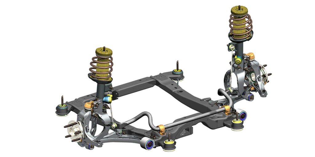
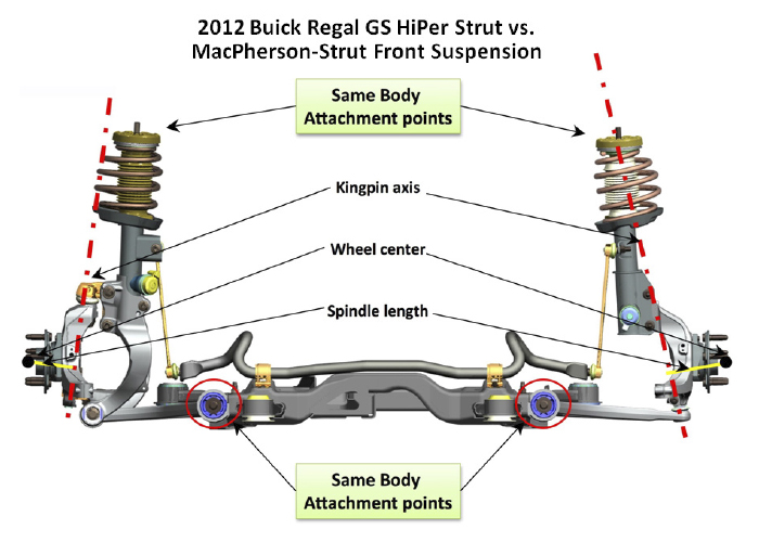
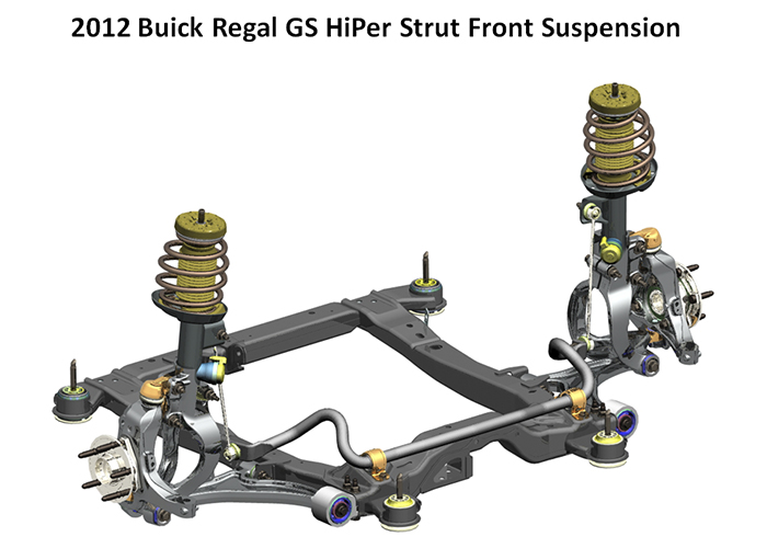
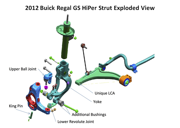
The Toyota Super Strut of the 1990s, GM’s HiPer Strut and Ford’s RevoKnuckle optimize the scrub radius and SAI by mounting a steering knuckle onto the side of the strut using ball joints. This makes the steering axis more upright when compared to the geometry of an upper strut mount and lower ball joint. Some call this a dual-path design because the SAI and steering axes are no longer connected. This reduces the scrub radius and brings it closer to the center of the contact patch. It also allows for larger brake and wheel packages.
Other recent designs for strut suspensions use two lower links with ball joints connected to the knuckle. These links or control arms have different mounting points and lengths to change the suspension’s geometry when cornering or braking. The most recent example of this is the current generation of the Ford Mustang, introduced in 2015.
Alignment
A strut suspension will typically have tighter tolerances for the alignment angle than a short-long arm suspension. The amount or range of adjustment can also be limited by the number of mounting points on the vehicle. Also, since a strut suspension has fewer parts, the potential for one adjustment affecting another is greater. This is often the case with camber adjustments that can change the toe angles of a strut suspension. Some alignment professionals call this “cross-talk.”
The other factor that needs to be considered is the unibody and subframe. Most vehicles use a strut tower that is part of the unibody and a subframe to mount the lower control arms. While it is rare for the subframe to shift due to a collision, or the mounts and bushings to degrade.